4.8 KiB
Input devices
Group assignment && individual assignment
We first tested with the oscilloscopes and a potentiometer. We connected the potentiometer to A oscilloscope and a arduino to digital read it and analog read it.
The more we pushed the potentiometer the higher the voltage became. So the voltage drop was decreasing and that was visible on the oscilloscope.
Later on Henk connected a ds18b20 to a signal analyzer and tried reading the protocol.
Potentiometer/Joysticks
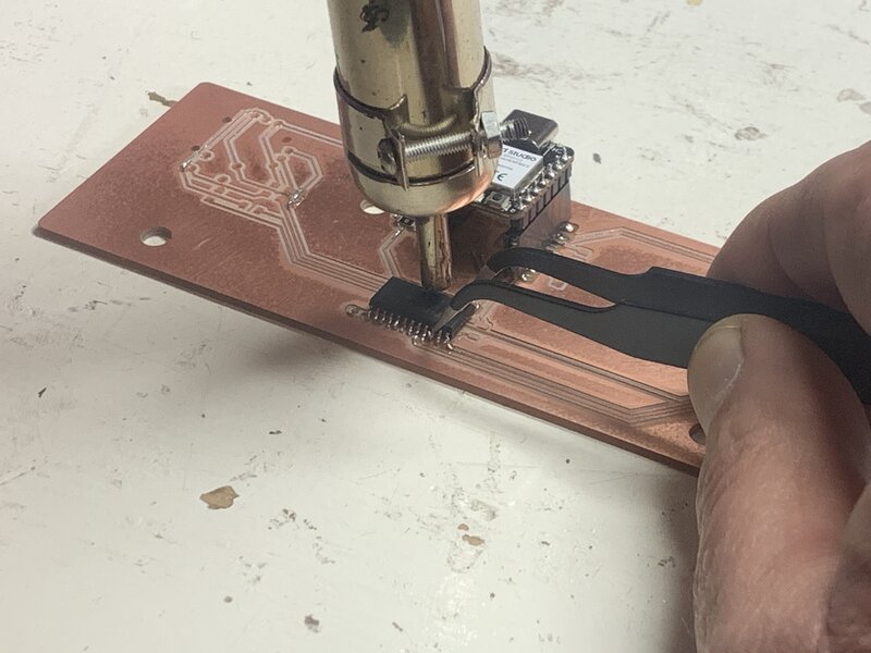
For this week I want to get proper readings from my joysticks. I got them from aliexpress and couldn't find any datasheets on them. So I gotta test them out myself. With 3.3 volts I got good measurements when sliding the joystick to the lest and bad measurements when going to the right. When fully to the right it was hanging around 2400 and sometimes jittering to 2700. With a controller for a drone I don't want any jittering so I need to figure out how to make them completely stable. On my first board I had a lot of errors. When I was soldering the multiplexer the first time I accidentally rotated it 180 degrees. So I asked Henk for help de-soldering it.

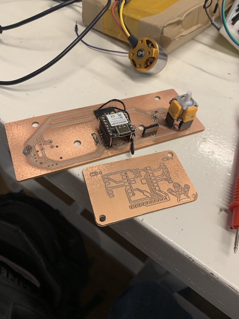
 This was my setup of my first board. The multiplexer worked straight away luckily but getting good readings from the joystick was a a lot harder than I thought. Because I couldn't get to 0 and was getting jitters.
With my second board I implemented a 5v voltage regulator. But after testing it my mcu kept reporting 0 to 3 millivolts on the pin. Which was odd. When I placed my multimeter between the input pin and the ground it reported 2.5 volts.

 When fully to the right it won't drop to 0 but when to the left it goes to 4095 on the edge so I thought it maybe was that it needed 5v instead of 3.3v.
So now I wanna test on a arduino to see if it works right on 5 volts. If it does I need to figure something out to either get 5v on the esp of another way of communicating between another mcu and esp. I can't use the VIN of the esp because I want to use batteries. When using batteries there isn't going to be 5v supplied on the VIN. Or maybe I should use a power bank. Then I do have 5v out.
Using 5v with the arduino I get a lot more stable values. So now I need to try 5v with the esp and attempt to read it. If that works I am going to use the VIN for 5v supply.
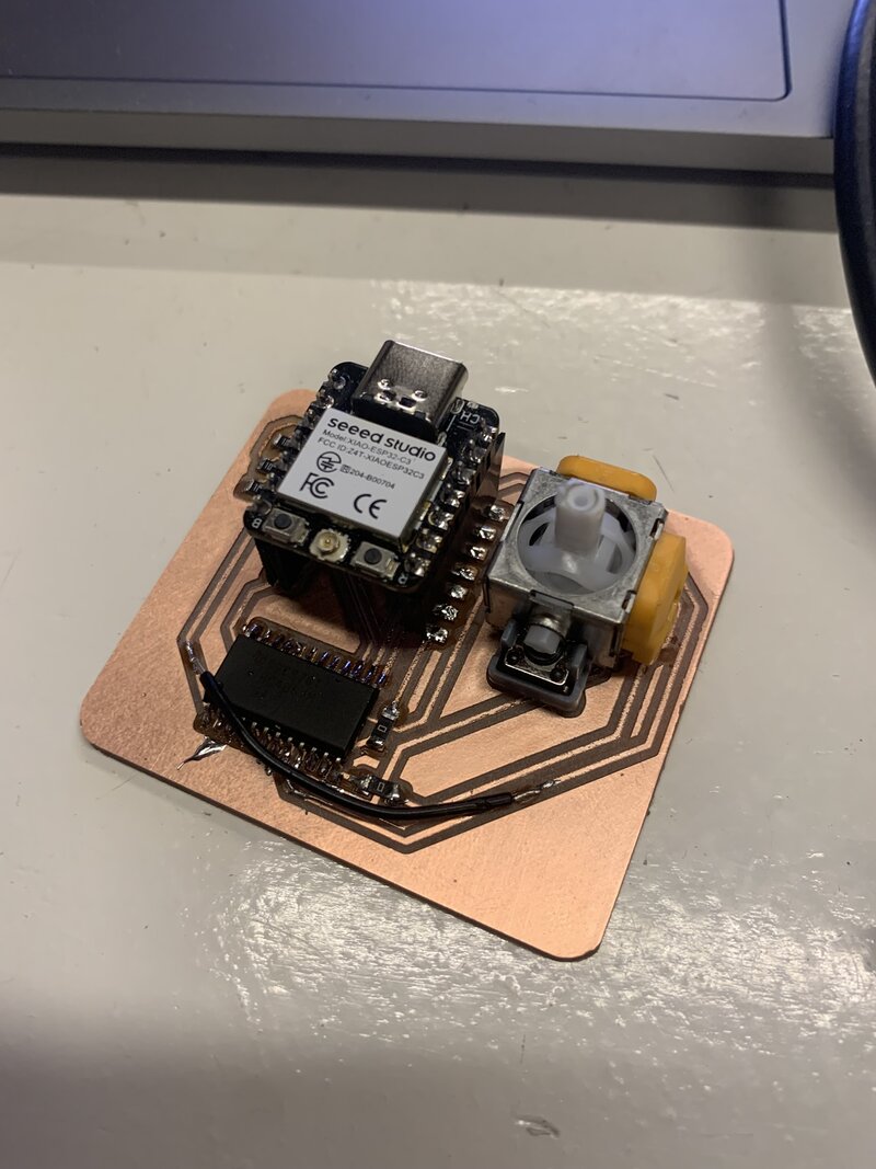
When testing with the esp and bridging the wires I realised something. Maybe the multiplexer also needs 5v to forward anything below 5 volts. So I milled a new board with 5v supply to the multiplexer. With this design.
After debugging for a while Henk asked me what was wrong and then it all clicked. I went to re read the documentation on how voltage dividers worked from this website and I then it all clicked. I first needed the lower Ohm to the input pin and then before the ground a higher resistor. So like this
 Instead of this.
 This is still a bit complicated because I am using 2 resistors at the ground because I needed 20K Ohm but we only had 10K Ohm so I set 2 10K Ohm in series to create 20K Ohm.
During debugging I first removed the multiplexer and created a bypass to attempt to isolate the problem.

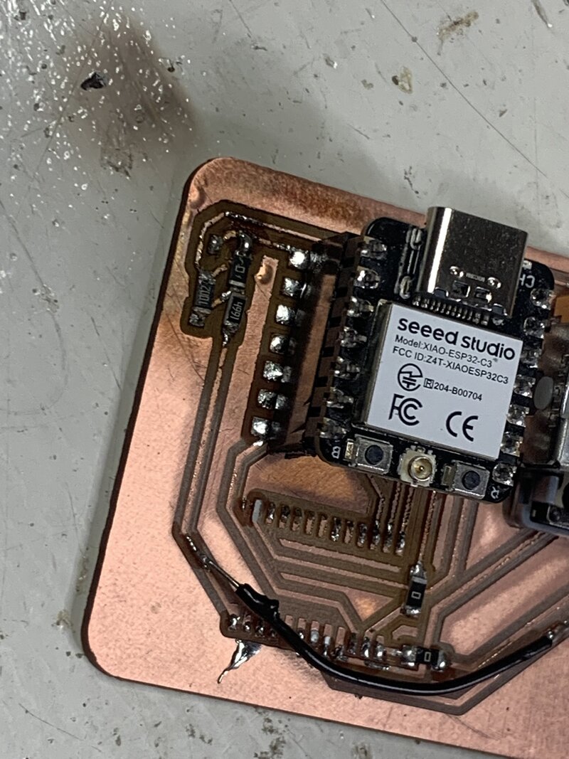
Then I still struggled the entire day debugging and then I gave up and went home. In the morning Henk used the rubber ducky method and I found the problem and fixed it like this.
Before

 It looks super messy but what I have done is. I broke one trace and created the same configuration as in the correct schematic. I connected the resistors wrongly and that caused all the power to go to ground instead of dividing the voltage to the analog pin and the ground.
Now that this works I can work on the final design of the board and send it to a board house.
Voltage divider
This week I learned how voltage dividers worked and I also struggled a lot with them. A voltage divider is better for splitting voltage instead of creating a voltage drop using a single resistor. Because you don't have to know how much current is flowing. Instead you can divide the voltage between 2 lanes.
 I found a lot of helpfull explanation on this website.


