8.6 KiB
Idea final project
Introduction
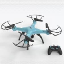
I wanted to combine 2 random objects that interest me into one project. A drone and a jumbotron. So im gonna make a drone with multiple screens on it that could for example be used for traffic control or entertainment purposes.
What does the drone do?
The drone needs to be able to fly for at least 20 minutes. It needs 2 screens on both side so it can display images or video. I wanna program the drone myself so I know how drones work and how they keep themselves upright.
Drone Requirements
basic requirements
- 2 screens
- Speakers
- 20 min flight time
- custom microcontroller pcb that controls the drones and screens
- 50 meter range from controller
Sensors
- GPS
- IMU/rotation sensor
- Read voltage from battery know battery percentage
Requirements when far ahead
- Docking station
- Automatic docking
- Automatic pathing
- Design own electronic speed controllers
Images
Drawing the drone
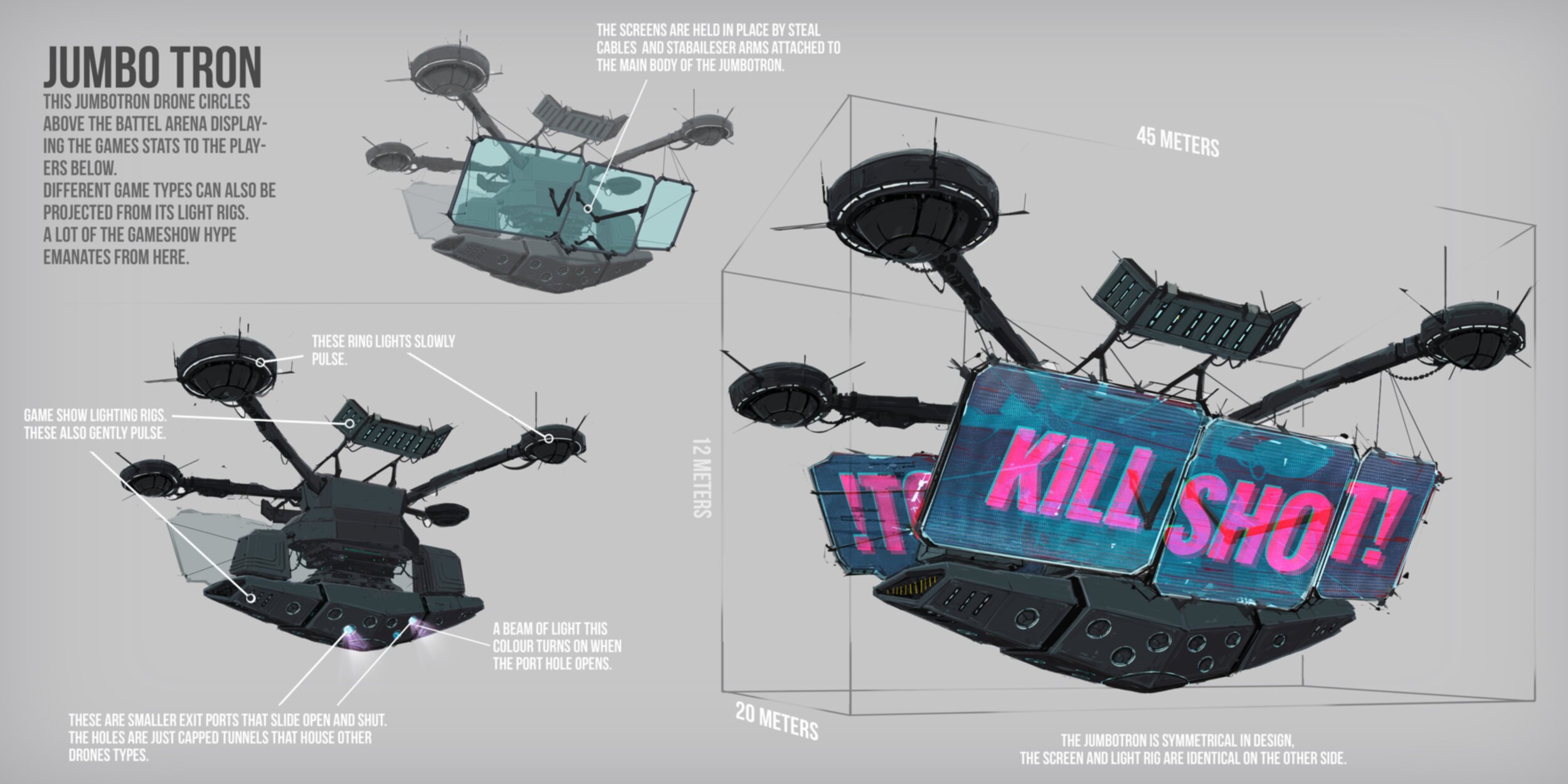
I have a few concept images above and this is the result my drawings.
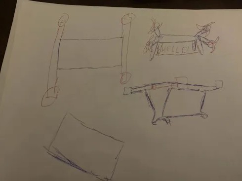
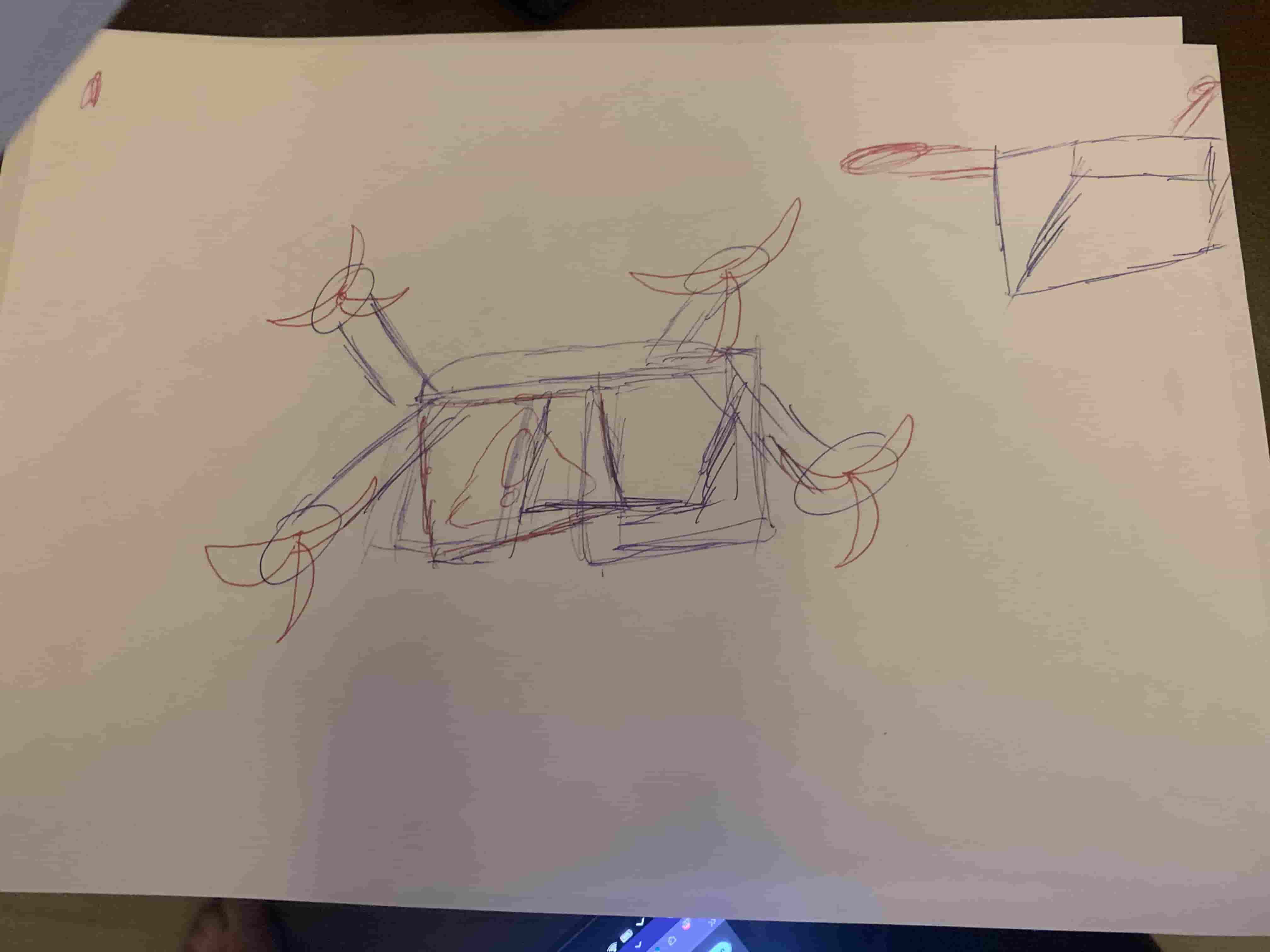
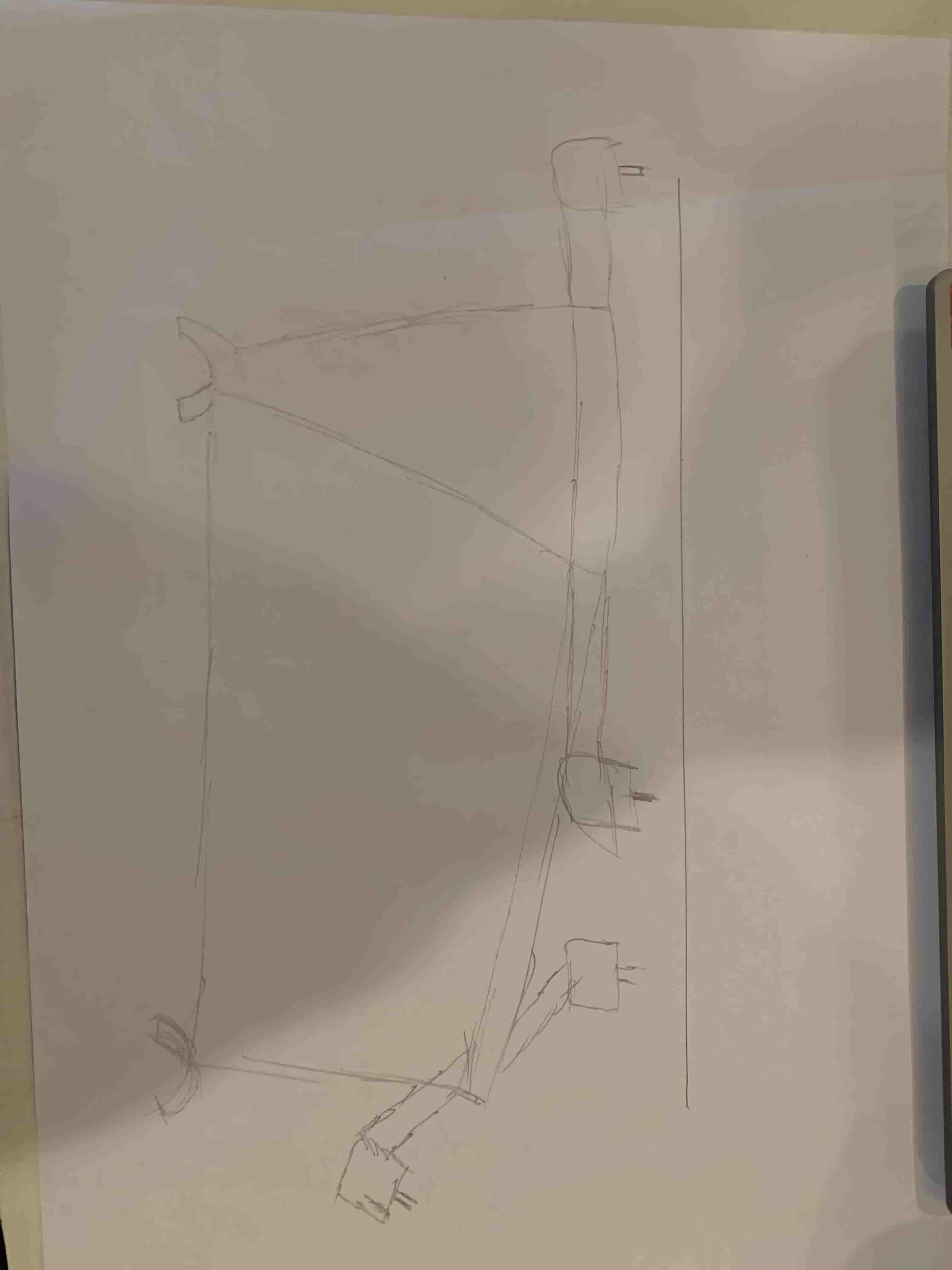
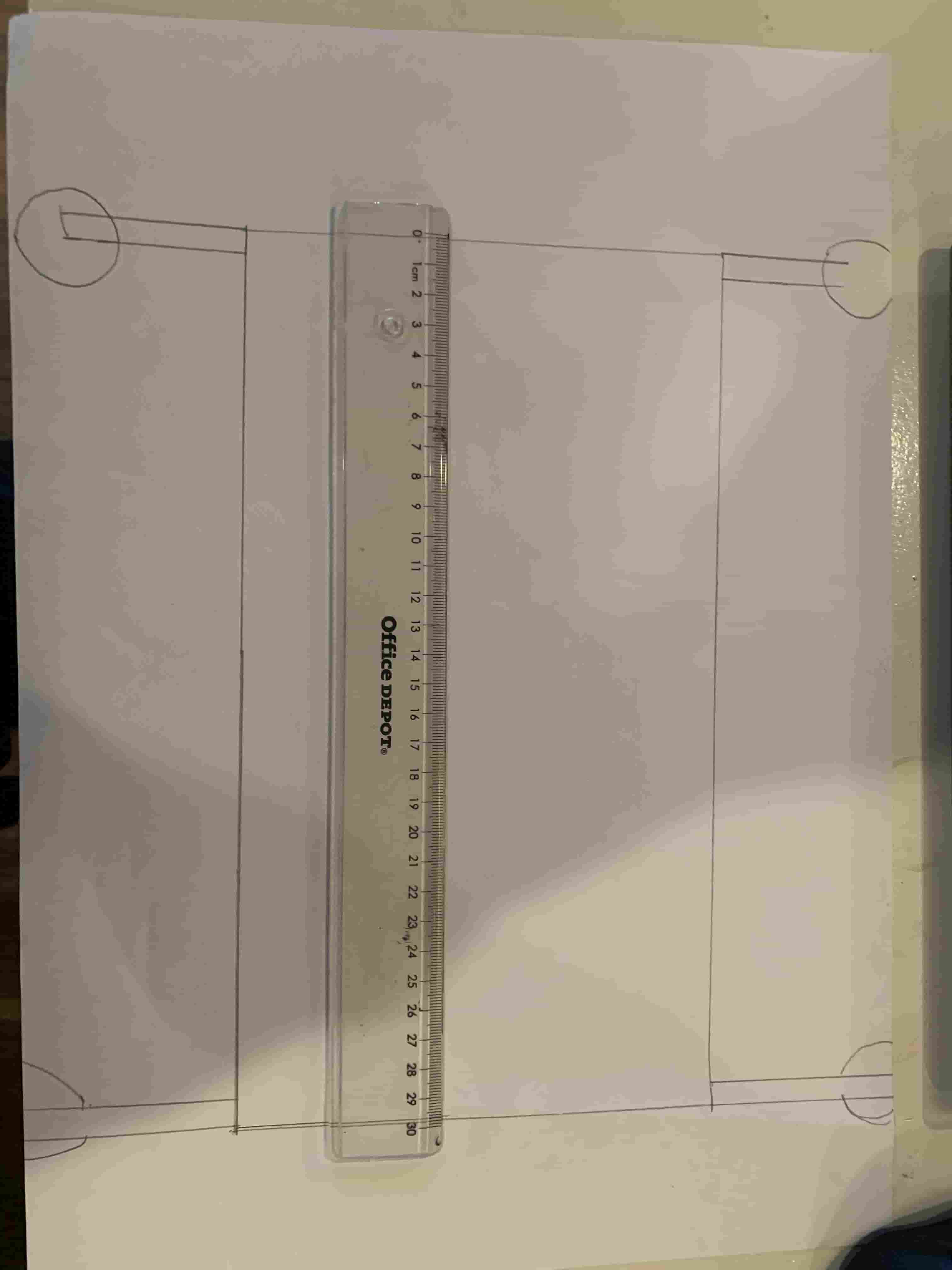
In the second picture you can see that I wanted to make the drone 30 cm in length. But then I looked at the prices for bigger batteries and it started to get super expansive real fast. So I decided to make it smaller. So now im planning on making a drone 10 cm in length. Im still going for the design in the third image. You can also kinda see that I got my inspiration from the third concept art image. And im giving my on twist on it.
Designing the drone
When designing the drone I wanted to do everything parametric. So im going to try to use as much variables as possible and make everything depend on each other so everything automatically scales when I change one parameter.
Designing the drone parametrically
Designing parametrically is very hard because every constraint needs to be perfect. Otherwise when changing lengths the design will fold into itself like this.
 I've spend one day getting the constraints perfect for the sketch so it scales well with everything. And this is the result of that. When I change one parameter in the variable menu the entire body scales with it. This is the final result of my design. I've made the body myself and I've imported the components from grabcad. So I had more time for blender and Onshape and so I could visualize it better.

Rendering
I've also made a render of the drone to visualize it for other people. Making this was kind of a pain because blender is a gigantic program. You can see my docs to see where I struggled. This is my final result of the render. I've wished it looked nicer but I didn't have enough time to dive deeper into blender.
Feedback from Bas and Henk
I've gotten some feedback on my design and about the use of screens. Maybe I should only use speakers or use LED matrixes. After thinking about it I think im going to give LED matrixes a spin.
Drone electronics
For the drone I will need a lot of electronics. But I will also need a pcb for inside the drone so I don't have any loose connections. The main board needs a couple of components. Something to step down the voltage from the big battery or I will use two separate batteries one for the motors one for the control board. I will also need a sensor to know the position of the drone and a microcontroller. I also need a lot of power to power the screens so that will also be something interesting.
Components
- MCU
- BNO085
- Something to drive the LED matrixes
- SD card/ secondary MCU to control the matrixes
- LED (mandatory)
Drone remote electronics
I'm also building the remote for the drone
- Potslider for the throttle
- Joystick for left-right-forward-backwards
- battery
- screen to see status of drone
- LED (mandatory)
Joystick
I really wanna use a joystick for this project because having 2 potmeters under each other looks a bit weird.
KiCad
The first thing I did was import the design rules for our milling machine. I used the file from the lecture to import it from because there we set everything up together.
Now im going to grab all the components needed for the board
- Joystick x2
- LED
- small oled screen
- xiao espS3
I was struggling a lot when thinking on how to connect the joysticks because the data sheet says it needs 5 volts. Until I realized they where potentiometers and they should work with any voltage. So I could directly connect the Joysticks to the MCU
Instead of it looking like this.
 This configuration wouldn't have worked anyway because the voltage regulator forces the voltage to 3.3 so the mcu will only read one value.
It now looks like this:
 So I have 2 joysticks that are directly connected to the mcu. A screen that works on the I2C protocol and a LED.
First when routing the joysticks I realized that the Xiao has analog on both sides of the board. So if I change the schematic so it connects to the other side I have a lot less longer traces.
 So like this instead of needing them to go across the entire mcu.
I forgot to apply the design rules so I imported them again and now I have to retrace everything. Thanks Irja for checking them together.
Then I needed to draw the outlines. To draw curved lines I used this tutorial. It's hard to get the get everything symmetrical. Maybe there is already a tool to do that but I don't know where to find it.
This is the result of the board.
After some weeks I changed the design to this. Because I noticed the esp-C3 doesn't have enough analog pins for my joysticks so I asked Henk if I could use one of their esp-S3's because it had a lot more analog pins.
 ESP S3
 ESP C3
 New design
This new design also saves a lot on material because the legs don't have to be cut out so I can almost make twice as many boards with the same material.

I've also send this board to JLCPCB for FR04 fabrication. Because I had issues where my FR-1 copper would just let got when moving the joysticks around. I wanted the controller to be super reliable and durable so that's why I ordered them from JLCPCB
Programming
For the drone I will be using the dRehmFlight VTOL program. In the programming week I already modified it to support the BNO085 and made the bridge between my handheld controller and the flight controller using ESPNow. For further support I still had some bugs to squash and some other features to implement for compatibility with my system.
classDiagram
namespace Drone {
    class ESPC6 Thread 1{
        +Control Motors
        +keep drone in the air
        +Receive communication from controller
        Flightcontroller()
    }
    class MatrixControllerThread2 {

    }

}

namespace Controller {
    class ESPC3 {
        +Read joystick data
        +Clean joystick data
        +Send joystick data to the drone
        Handheld Controller()
    }
}

ESPC3 --> ESPC6 Thread 1 : Send data to flight controller using ESPNOW
I've already gotten the motors to spin in week 10 using the script in there. Now I also need to modify the driver so my ESC's can properly understand it's instructions.
https://grabcad.com/library/readytosky-rs2205-1
TODO
- Matrix board subsystem
- Rewrite PWM esc control system in driver
- Does it fly?
- Power distribution system (for matrixes and mcu's)
- Test physical controller
BOM (bill of materials)
| item | price | link |
|---|---|---|
| item1 | 999 | link.com |

